The board drives the valve
The parcel I was waiting on at the end of last time turned up on the Friday it was promised, which meant I could finally finish populating the board — and then do the thing this whole project has been building towards. I put the real soldered board on the bench next to the CWX-15Q, flipped the switch, and it drove the valve: open, stop, closed, stop. Exactly what the breadboard did, only now it's a board I made.
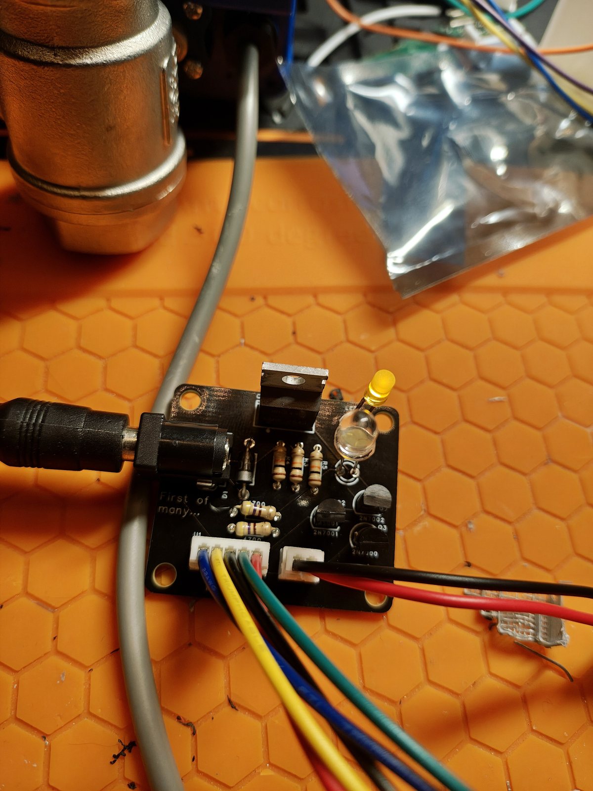
Finishing the board
The missing half of the BOM — the JST PH connector kit and the R1–R5 resistors — arrived together, no drama for once. The PH connectors went into the footprints they were always meant for (turns out the holes fit when you order the right pitch), and the resistors dropped in after them: R1 and R2 for the LEDs, R3–R5 as the gate resistors. The good silver wire from Kjell made the last few joints as painless as the first batch.
So that's the whole board: barrel jack, the IRF610, three 2N7000s, the flyback diode, both LEDs, five resistors and the two JST connectors. Every footprint filled, nothing left bare. After two posts of "the board exists but I can't build it yet," it is genuinely satisfying to have one that's just done.
On the bench with the valve
Wiring up the test was three connectors. 12 V into the barrel jack, the switch onto the 2-pin CN1, and the valve's five CR05 wires onto the 5-pin U1 — two for the motor, three for the limit switches. That last connector is the whole reason the board has to know which way it last drove the valve, so it can cut the motor at the right end.
And it just worked. Flip the switch one way and the motor runs the valve open until the open-end limit switch cuts it; flip it back and it drives closed until the other limit switch stops it. No babysitting, no manual power-cycling — the board drives to the end I asked for and stops itself, which is exactly the trick the four transistors are there to do. The two LEDs report which way I last sent it, same as on the breadboard.
The toggle I'm flipping in the video is the switch I'll actually install — one switch, two positions, open and closed. Here it is doing the rounds on the bench:
What's next
The electronics chapter is basically closed: the circuit works on a board I built, driving the real valve, off a single switch. What it doesn't have yet is anywhere to live. The next job is an enclosure — something to hold the board and mount the switch so the whole thing isn't a bare PCB and a toggle loose on a bench. Then it's the actual install at the summer house, with the switch somewhere I can reach standing up instead of half a metre down under a shelf.
Standing caveats, unchanged: this still hasn't met a Swedish January or a drop of water, and right now it lives on a silicone mat, not in a box on a wall. But it drives the valve, and that's the part I wasn't sure I could build. Wi-Fi stays where it's always been — behind the rule that the dumb version has to survive a winter first.